De-clip
De-clip repairs digital and analog clipping artifacts that result when A/D converters are pushed too hard or magnetic tape is over-saturated.
Jan 02, 2016 Teil 2 der Videostrecke zu iZotope RX 5. In diesem Teil: Das De-clip-Modul, sowie der allgemeine Umgang mit den Modulen Der Artikel auf Recording.de: http://. Jan 24, 2020 iZotope RX (iZotope RX 2.exe). IZotope RX is a very powerful application designed to help its users repair audio files. This program offers an impressive amount of handy functions like denoise, spectral repair, remove hum, declip etc. Clip Gain is a non-destructive amplitude envelope drawn into the main display. It's intended for levelling inconsistent audio but can also be used for creative effects, too. Hit Ctrl/Cmd-G to reveal the white Clip Gain line in the middle of RX 4's editor, then click it to create a node that you can drag upwards for up to 36dB of gain, or down.
De-clip can be extremely useful for rescuing recordings that were made in a single pass, such as live concerts or interviews, momentary overs in 'perfect takes', and any other audio that cannot be re-recorded.
De-clip will process any audio above a given threshold, interpolating the waveform to be more round. Generally, the process is as easy as finding the clipping you want to repair, then setting the threshold just under the level where the signal clips.
You can find clipping by either listening for the distortion that clipping causes, or finding the high harmonic overtones of distortion in the spectrogram.
A waveform before and after clip repair. The after example (bottom) shows the original repaired waveform (faded) and the post-limiting waveform (bright).
Histogram Meter
Displays waveform levels for the current selection as a histogram.
The histogram meter helps you set the Threshold control by displaying the audio level where the waveform's peaks are concentrated. This usually indicates at what level clipping is present in the file.
A histogram is an analytical tool that displays how many samples are present at a given signal level over a window in time. The longer the line for the histogram is, the more energy is present at that amplitude. If a lot of energy tends to collect near the top and bottom edges of a waveform, that waveform is probably clipped and distorted.
Clipped peaks in waveform, with histogram from selection
In the RX Application, select a section of the recording where clipping is prominent and De-clip will analyze the levels of the program material. If clipping is present in the selection, it will usually appear as a horizontal line in the histogram that extends all the way across the meter.
In the RX Plug-in, the histogram runs as a realtime meter.
The histogram’s range can be scaled if you need a better view of your signal. Use the (+) and (-) buttons to scale your display and value resolution for the De-clip module. These buttons reduce (+) and/or expand (-) the range of the threshold slider and histogram. You may want to extend the histogram range when your clipping point is lower than what you can see on a histogram or if you don’t see anything on the histogram.
If you are using the De-clip control overlay on the waveform display, you can use the mouse’s scroll wheel on the waveform amplitude scale to adjust the threshold control resolution.

Threshold [dB]
Selects the clipping level used for detection of clipped intervals. Generally, this should be set just below the actual level of clipping.
Note: adjusting the Clipping Threshold will display a blue line within the histogram and a gray line on the waveform itself. This gray line shows the level on the waveform above which the De-clip algorithm will process the audio file. All sections of the waveform above this level will be regarded as clipping. Within the histogram itself the elements of the file that will be processed (above the blue line) will appear gray.
To set the threshold, move the Threshold slider until it lines up with the place in the histogram just below where clipping is concentrated.
In the RX Application, you can set the Threshold slider automatically with the Suggest button.
You can also set the clipping threshold from the RX waveform display. By default, De-clip Threshold is enabled in the Effect Overlays section of the View menu. When this option is enabled, you can see the relationship of the De-clip Clipping Threshold settings to your file’s waveform, and make adjustments to the setting by clicking and dragging on the red threshold line.
If you would like greater control resolution or need to apply De-clipping to a different amplitude range, you can adjust the amplitude range of the waveform display by using the zoom control, clicking and dragging the amplitude ruler, or using your mouse’s scroll wheel over the amplitude ruler.
Threshold Link

Toggles the ability to adjust positive and negative clipping thresholds independently.
When this option is enabled, you can adjust the positive and negative clipping Threshold controls independently. This is useful in cases where more clipping is occurring on one side of your waveform.
You can also set asymmetric de-clipping thresholds directly from the waveform by toggling the lock box between the threshold controls on the waveform display.
This problematic waveform (grey) shears off around −13 dB on only the positive side of the waveform (the histogram on the right shows the extra positive energy of clipped audio). Extra processing of the negative side would be unnecessary, so the Threshold controls can be unlinked to process above −13 dBFS on the positive side only. The resulting waveform is drawn in blue above the grey sheared peak.
Suggest

Calculates suggested threshold values based on the levels in your current selection.
Izotope Rx Remove Clip Gain Node List
Quality
Controls the interpolation processing quality.
There are three quality modes in RX's De-clip: Low, Medium, and High. Low quality mode processes very quickly; High quality mode processes slowly but is capable of achieving better results. In many cases you will find that Low quality mode gives you great results. To save time, always start by previewing the Low quality modes first. You can also use the Compare feature to try multiple modes and preview the results.
Makeup gain (dB)
Selects the gain to be applied to the selection after De-clip.
The De-clip process causes an increase in peak levels. The Makeup gain control can be used to prevent the signal from clipping after processing. It is also useful for matching the level after processing to unprocessed audio outside of the selection.
Izotope Rx Remove Clip Gain Node In Back
Post-limiter
Applies a true peak limiter after processing to prevent the processed signal from exceeding 0 dBFS.
De-clip usually increases signal levels by interpolating signal segments 'above' the clipping point, which can make the signal clip again if the waveform format offers no headroom above 0 dBFS.
If the post-limiter is disabled, the restored intervals above 0 dBFS can be safely stored even without makeup gain as long as the file is saved as 32-bit float. Intervals above 0 dBFS will clip when played back through a digital-analog converter.
Suggestions for severe distortion
For certain situations, using the Deconstruct module to extract the noise components of the distortion can help remove additional artifacts beyond the clipped peaks in a waveform. In cases where severe distortion is visible on the spectrogram, the Spectral Repair tool can be used to select those problem areas, and attenuate or replace them with undistorted audio.
Overview
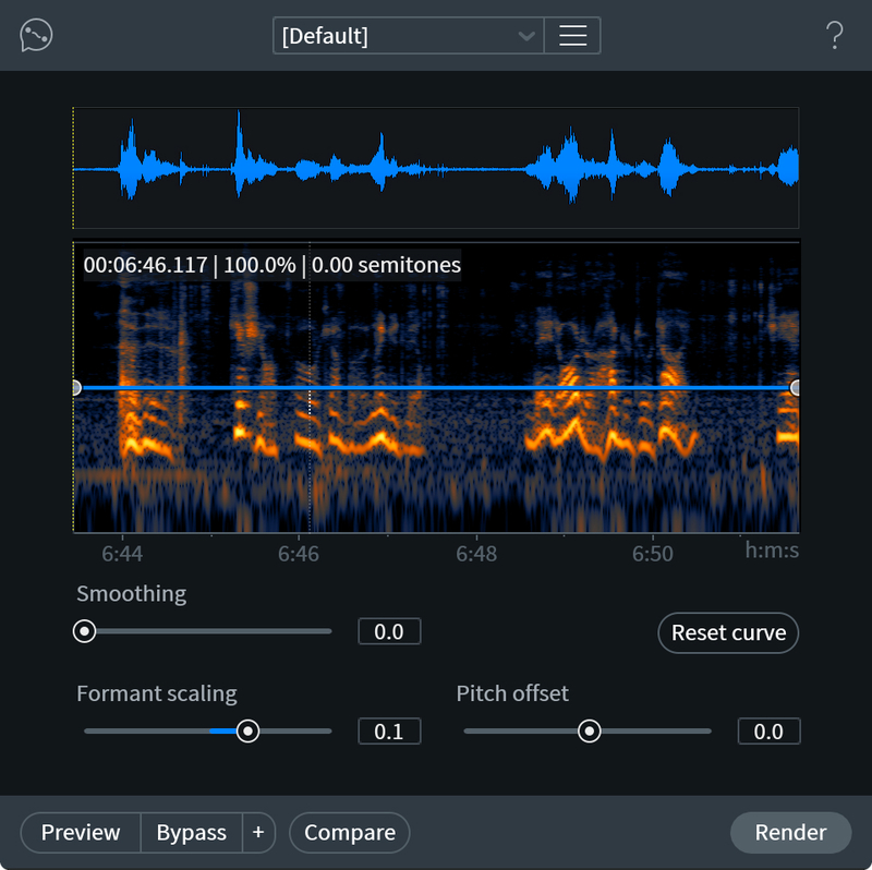
The Pitch Contour module lets you change the pitch of a selection over time. This can be used to quickly correct small pitch variations or gradual pitch drifts over time.
The Pitch Contour module changes pitch by continuously changing the playback speed of the audio. The effect is similar to speeding up or slowing down a record or tape deck while it is playing back.
The Pitch Contour module uses resampling to synchronously change the time and pitch of a selection, because of this it cannot be used to adjust pitch without also adjusting time.
Controls
Smoothing: Larger values create a smoother pitch curve when multiple pitch nodes are present. This is useful when correcting a nonlinear change in pitch.
Izotope Rx 7 Free Download
Reset: Clears all pitch nodes and returns the Smoothing control to its default value.
Pitch Contour graph
Izotope Rx Free Trial
- The horizontal axis shows time in seconds. The range of the horizontal axis will reflect the length of your current selection. If you have no selection, the horizontal axis represents the entire length of your file.
- The vertical axis shows the amount of pitch shifting that will be applied. A curve through the top half of the display will create a higher shift in pitch and shorten the audio correspondingly. A curve through the lower half of the display will create a lower shift in pitch and lengthen the audio correspondingly.
- You can correct a gradual pitch drift over time by adjusting the points at the far left or right of the display, drawing a straight sloping line from the beginning of your selection to the end. These points are locked to the vertical axis
Tip
Izotope Rx Download
- Clicking on the contour display will create a new pitch node. You can create up to 20 pitch nodes to achieve very complicated pitch shifts.
- Clicking and dragging a pitch node to move it around will change the pitch curve.
- Double-clicking on a pitch node will set its value to 0 (no change at that point).
- Right-clicking on a pitch node will delete it.
- Holding control/command while dragging will give you fine control over a pitch node’s position.